Trimmer (electronics)
This article needs additional citations for verification. (May 2008) |

A trimmer, or preset, is a miniature adjustable electrical component. It is meant to be set correctly when installed in some device, and never seen or adjusted by the device's user. Trimmers can be variable resistors (potentiometers), variable capacitors, or trimmable inductors. They are common in precision circuitry like A/V components, and may need to be adjusted when the equipment is serviced. Trimpots (trimmer potentiometers) are often used to initially calibrate equipment after manufacturing. Unlike many other variable controls, trimmers are mounted directly on circuit boards, turned with a small screwdriver and rated for many fewer adjustments over their lifetime. Trimmers like trimmable inductors and trimmable capacitors are usually found in superhet radio and television receivers, in the intermediate frequency (IF), oscillator and radio frequency (RF) circuits. They are adjusted into the right position during the alignment procedure of the receiver.
General considerations
[edit]Trimmers come in a variety of sizes and levels of precision. For example, multi-turn trim potentiometers exist, in which it takes several turns of the adjustment screw to reach the end value. This allows for very high degrees of accuracy. Often they make use of a worm-gear (rotary track) or a leadscrew (linear track).[1]
The position on the component of the adjustment often needs to be considered for accessibility after the circuit is assembled. Both top- and side-adjust trimmers are available to facilitate this. The adjustment of presets is often fixed in place with sealing wax after the adjustment is made to prevent movement by vibration. This also serves as an indication if the device has been tampered with.
Resistors
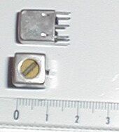
[edit]Resistor trimmers generally come in the form of a potentiometer (pot), often called a trimpot. Potentiometers have three terminals, but can be used as a normal two-terminal resistor by joining the wiper to one of the other terminals, or just using two terminals. Trimpot is a registered trademark of Bourns, Inc.,[2] and the device was patented by Marlan Bourns in 1952. The term has since become generic.
Two types of preset resistor are commonly found in circuits. The skeleton potentiometer works like a regular circular potentiometer, but is stripped of its enclosure, shaft, and fixings. The full movement of a skeleton potentiometer is less than a single turn. The other type is the multi-turn potentiometer which moves the slider along the resistive track via a gearing arrangement. The gearing is such that multiple turns of the adjustment screw are required to move the slider the full distance along the resistive track, leading to very high precision of setting. Some, possibly the majority, of multi-turn pots have a linear track rather than a circular one.[3]: 86 Typically, a worm gear is used with rotary track presets and a leadscrew is used with linear track presets.[1]
 |
 |
 |
 |
 |
Capacitors
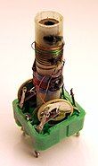
[edit]Trimming capacitors can be multi-plate parallel-plate capacitors with a dielectric for between plates for increased capacitance. However, at SHF only very small values of capacitance are needed. Presets at these frequencies are commonly a glass tube with plates at either end. The top plate is adjusted by means of a screw to which it is attached at the top of the cylinder.
Inductors
[edit]A common way of making preset inductors in radios is to wind the inductor on a plastic tube. A high permeability core material is inserted into the cylinder in the form of a screw. Winding the core further in to the inductor increases inductance and vice versa. It is normally necessary to use non-metallic tools to adjust inductors. A steel screwdriver will increase the inductance while it is being adjusted and it will fall again when the screwdriver is removed.
At VHF and SHF, only small values of inductance are usually needed. Inductors can be made of open coils of a few turns. They can be tuned by squeezing the coils together or by pulling them apart as the inductance needs to be increased or decreased respectively.
Tuned circuits
[edit]An adjustable tuned circuit can be formed in the same way as a preset inductor. The inductor and its resonant capacitor are commonly contained in a metal can for shielding with a hole at the top to give access to the adjustable core. Tuned transformers can also be constructed this way with two windings on the same core. This is a common component in the IF stage of radios which have a double-tuned amplifier format.
 |
 |
 |
Distributed-element circuit
[edit]Distributed-element circuits often use the component known as a stub. In printed planar formats such as microstrip, stubs can be trimmed by removing material with a scalpel or adding material by soldering on copper foil or even just pressing on strips of indium. This is useful for prototypes and pre-production runs, but is usually not done on production items.
Applications
[edit]They are common in precision circuitry like A/V components, and may need to be adjusted when the equipment is serviced. Trimpots are often used to initially calibrate equipment after manufacturing. Unlike many other variable controls, trimmers are mounted directly on circuit boards, turned with a small screwdriver and rated for many fewer adjustments over their lifetime. Trimmers like trimmable inductors and trimmable capacitors are usually found in superhet radio and television receivers, in the intermediate frequency (IF), oscillator and radio frequency (RF) circuits. They are adjusted into the correct position during the alignment procedure.
Electronic symbols
[edit]
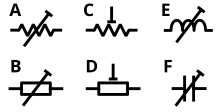
In circuit diagrams, the symbol for a variable component is the symbol for a fixed component with a diagonal line through it terminating in an arrow head. For a preset component, the diagonal line terminates in a bar.[3]: 86, 97
See also
[edit]References
[edit]- ^ a b "Trimpot - Trimmer potentiometer". the Resistor Guide. Retrieved 20 February 2013.
- ^ U.S.P.T.O. Registration Number 0725309
- ^ a b E. Stocks, Malcom Doughton, C. Duncan, Basic Science and Electronics, Thomson Learning, 1998 ISBN 1861527594
External links
[edit]- Trimmer potentiometers (examples and internals), Robot Room
- Highlights from Trimmer Primers - Bourns
