Groundwater model
Groundwater models are computer models of groundwater flow systems, and are used by hydrologists and hydrogeologists. Groundwater models are used to simulate and predict aquifer conditions.
Characteristics
[edit]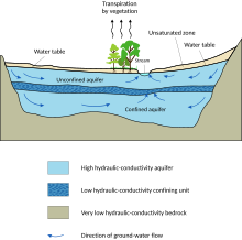
An unambiguous definition of "groundwater model" is difficult to give, but there are many common characteristics.
A groundwater model may be a scale model or an electric model of a groundwater situation or aquifer. Groundwater models are used to represent the natural groundwater flow in the environment. Some groundwater models include (chemical) quality aspects of the groundwater. Such groundwater models try to predict the fate and movement of the chemical in natural, urban or hypothetical scenario.
Groundwater models may be used to predict the effects of hydrological changes (like groundwater pumping or irrigation developments) on the behavior of the aquifer and are often named groundwater simulation models. Groundwater models are used in various water management plans for urban areas.
As the computations in mathematical groundwater models are based on groundwater flow equations, which are differential equations that can often be solved only by approximate methods using a numerical analysis, these models are also called mathematical, numerical, or computational groundwater models.[1]
The mathematical or the numerical models are usually based on the real physics the groundwater flow follows. These mathematical equations are solved using numerical codes such as MODFLOW, ParFlow, HydroGeoSphere, OpenGeoSys etc. Various types of numerical solutions like the finite difference method and the finite element method are discussed in the article on "Hydrogeology".
Inputs
[edit]For the calculations one needs inputs like:
- hydrological inputs,
- operational inputs,
- external conditions: initial and boundary conditions,
- (hydraulic) parameters.
The model may have chemical components like water salinity, soil salinity and other quality indicators of water and soil, for which inputs may also be needed.
Hydrological inputs
[edit]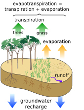
The primary coupling between groundwater and hydrological inputs is the unsaturated zone or vadose zone. The soil acts to partition hydrological inputs such as rainfall or snowmelt into surface runoff, soil moisture, evapotranspiration and groundwater recharge. Flows through the unsaturated zone that couple surface water to soil moisture and groundwater can be upward or downward, depending upon the gradient of hydraulic head in the soil, can be modeled using the numerical solution of Richards' equation[2] partial differential equation, or the ordinary differential equation Finite Water-Content method [3] as validated for modeling groundwater and vadose zone interactions.[4]
Operational inputs
[edit]The operational inputs concern human interferences with the water management like irrigation, drainage, pumping from wells, watertable control, and the operation of retention or infiltration basins, which are often of an hydrological nature.
These inputs may also vary in time and space.
Many groundwater models are made for the purpose of assessing the effects hydraulic engineering measures.
Boundary and initial conditions
[edit]
Boundary conditions can be related to levels of the water table, artesian pressures, and hydraulic head along the boundaries of the model on the one hand (the head conditions), or to groundwater inflows and outflows along the boundaries of the model on the other hand (the flow conditions). This may also include quality aspects of the water like salinity.
The initial conditions refer to initial values of elements that may increase or decrease in the course of the time inside the model domain and they cover largely the same phenomena as the boundary conditions do.
The initial and boundary conditions may vary from place to place. The boundary conditions may be kept either constant or be made variable in time.
Parameters
[edit]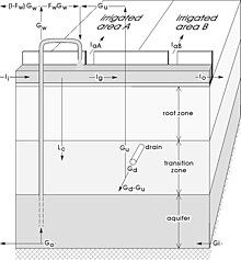
The parameters usually concern the geometry of and distances in the domain to be modelled and those physical properties of the aquifer that are more or less constant with time but that may be variable in space.
Important parameters are the topography, thicknesses of soil / rock layers and their horizontal/vertical hydraulic conductivity (permeability for water), aquifer transmissivity and resistance, aquifer porosity and storage coefficient, as well as the capillarity of the unsaturated zone. For more details see the article on hydrogeology.
Some parameters may be influenced by changes in the groundwater situation, like the thickness of a soil layer that may reduce when the water table drops and/the hydraulic pressure is reduced. This phenomenon is called subsidence. The thickness, in this case, is variable in time and not a parameter proper.
Applicability
[edit]The applicability of a groundwater model to a real situation depends on the accuracy of the input data and the parameters. Determination of these requires considerable study, like collection of hydrological data (rainfall, evapotranspiration, irrigation, drainage) and determination of the parameters mentioned before including pumping tests. As many parameters are quite variable in space, expert judgment is needed to arrive at representative values.
The models can also be used for the if-then analysis: if the value of a parameter is A, then what is the result, and if the value of the parameter is B instead, what is the influence? This analysis may be sufficient to obtain a rough impression of the groundwater behavior, but it can also serve to do a sensitivity analysis to answer the question: which factors have a great influence and which have less influence. With such information one may direct the efforts of investigation more to the influential factors.
When sufficient data have been assembled, it is possible to determine some of missing information by calibration. This implies that one assumes a range of values for the unknown or doubtful value of a certain parameter and one runs the model repeatedly while comparing results with known corresponding data. For example, if salinity figures of the groundwater are available and the value of hydraulic conductivity is uncertain, one assumes a range of conductivities and the selects that value of conductivity as "true" that yields salinity results close to the observed values, meaning that the groundwater flow as governed by the hydraulic conductivity is in agreement with the salinity conditions. This procedure is similar to the measurement of the flow in a river or canal by letting very saline water of a known salt concentration drip into the channel and measuring the resulting salt concentration downstream.
Dimensions
[edit]Groundwater models can be one-dimensional, two-dimensional, three-dimensional and semi-three-dimensional. Two and three-dimensional models can take into account the anisotropy of the aquifer with respect to the hydraulic conductivity, i.e. this property may vary in different directions.
One-, two- and three-dimensional
[edit]
- One-dimensional models can be used for the vertical flow in a system of parallel horizontal layers.
- Two-dimensional models apply to a vertical plane while it is assumed that the groundwater conditions repeat themselves in other parallel vertical planes (Fig. 4). Spacing equations of subsurface drains and the groundwater energy balance applied to drainage equations[5] are examples of two-dimensional groundwater models.
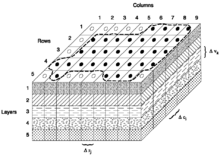
- Three-dimensional models like Modflow[6] require discretization of the entire flow domain. To that end the flow region must be subdivided into smaller elements (or cells), in both horizontal and vertical sense. Within each cell the parameters are maintained constant, but they may vary between the cells (Fig. 5). Using numerical solutions of groundwater flow equations, the flow of groundwater may be found as horizontal, vertical and, more often, as intermediate.
Semi three-dimensional
[edit]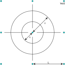
In semi 3-dimensional models the horizontal flow is described by 2-dimensional flow equations (i. e. in horizontal x and y direction). Vertical flows (in z-direction) are described (a) with a 1-dimensional flow equation, or (b) derived from a water balance of horizontal flows converting the excess of horizontally incoming over the horizontally outgoing groundwater into vertical flow under the assumption that water is incompressible.
There are two classes of semi 3-dimensional models:
- Continuous models or radial models consisting of 2 dimensional submodels in vertical radial planes intersecting each other in one single axis. The flow pattern is repeated in each vertical plane fanning out from the central axis.
- Discretized models or prismatic models consisting of submodels formed by vertical blocks or prisms for the horizontal flow combined with one or more methods of superposition of the vertical flow.
Continuous radial model
[edit]An example of a non-discretized radial model is the description of groundwater flow moving radially towards a deep well in a network of wells from which water is abstracted.[7] The radial flow passes through a vertical, cylindrical, cross-section representing the hydraulic equipotential of which the surface diminishes in the direction of the axis of intersection of the radial planes where the well is located.

Prismatically discretized model
[edit]Prismatically discretized models like SahysMod[8] have a grid over the land surface only. The 2-dimensional grid network consists of triangles, squares, rectangles or polygons. Hence, the flow domain is subdivided into vertical blocks or prisms. The prisms can be discretized into horizontal layers with different characteristics that may also vary between the prisms. The groundwater flow between neighboring prisms is calculated using 2-dimensional horizontal groundwater flow equations. Vertical flows are found by applying one-dimensional flow equations in a vertical sense, or they can be derived from the water balance: excess of horizontal inflow over horizontal outflow (or vice versa) is translated into vertical flow, as demonstrated in the article Hydrology (agriculture).
In semi 3-dimensional models, intermediate flow between horizontal and vertical is not modelled like in truly 3-dimensional models. Yet, like the truly 3-dimensional models, such models do permit the introduction of horizontal and vertical subsurface drainage systems.
Semiconfined aquifers with a slowly permeable layer overlying the aquifer (the aquitard) can be included in the model by simulating vertical flow through it under influence of an overpressure in the aquifer proper relative to the level of the watertable inside or above the aquitard.
Groundwater modeling software and references
[edit]- Analytic Element Method
- FEFLOW
- PORFLOW
- SVFlux
- FEHM
- HydroGeoSphere
- Integrated Water Flow Model
- MicroFEM
- MODFLOW
- OpenGeoSys
- SahysMod, Spatial agro-hydro-salinity-aquifer model, online: [8]
- US Geological Survey Water Resources Ground Water Software
- MARTHE from the French Geological Survey (BRGM)
- ZOOMQ3D
- Free groundwater modelling course for starters
See also
[edit]- Aquifer
- Groundwater
- Groundwater flow equation
- Groundwater energy balance
- Hydraulic conductivity
- Hydrogeology
- Salinity model
- Watertable control
- Groundwater drainage by wells
Footnotes
[edit]- ^ Rushton, K.R., 2003, Groundwater Hydrology: Conceptual and Computational Models. John Wiley and Sons Ltd. ISBN 0-470-85004-3
- ^ Richards, L. A. (1931), Capillary conduction of liquids through porous mediums, J. Appl. Phys., 1(5), 318–333.
- ^ Ogden, F. L., W. Lai, R. C. Steinke, J. Zhu, C. A. Talbot, and J. L. Wilson (2015), A new general 1-D vadose zone solution method, Water Resour. Res., 51, doi:10.1002/2015WR017126.
- ^ Ogden, F. L., W. Lai, R. C. Steinke, and J. Zhu (2015), Validation of finite water-content vadose zone dynamics method using column experiments with a moving water table and applied surface flux, Water Resour. Res., 51, doi:10.1002/2014WR016454.
- ^ The energy balance of groundwater flow applied to subsurface drainage in anisotropic soils by pipes or ditches with entrance resistance, International Institute for Land Reclamation and Improvement (ILRI), Wageningen, The Netherlands. Download from : [1], or directly as PDF : [2] Archived 2009-02-19 at the Wayback Machine Paper based on: R.J. Oosterbaan, J. Boonstra and K.V.G.K. Rao, 1996, The energy balance of groundwater flow. Published in V.P.Singh and B.Kumar (eds.), Subsurface-Water Hydrology, p. 153-160, Vol.2 of Proceedings of the International Conference on Hydrology and Water Resources, New Delhi, India, 1993. Kluwer Academic Publishers, Dordrecht, The Netherlands. ISBN 978-0-7923-3651-8. Download as PDF : [3] . The corresponding EnDrain model can be downloaded from: [4]
- ^ Online guide to MODFLOW-2000 and MODFLOW-2005
- ^ Subsurface drainage by (tube)wells: well spacing equations for fully and partially penetrating wells in uniform or layered aquifers with or without anisotropy and entrance resistance. Paper explaining the basics of the WellDrain model, International Institute for Land Reclamation and Improvement (ILRI), Wageningen, The Netherlands. Updated version of: R.J.Oosterbaan, Tube well spacing formulas for subsurface drainage. Published in: Smith, K.V.H. and D.W. Rycroft (eds.) Hydraulic Design in Water Resources Engineering: Land Drainage. Proceedings of the 2nd International Conference, Southampton University, p. 75‑84. Springer‑Verlag, Berlin, 1986. Download as PDF : [5] . Download the WellDrain model from: [6]
- ^ ILRI, 1995. SahysMod: Spatial Agro-Hydro-Salinity Model. Description of Principles, User Manual, and Case Studies. International Institute for Land Reclamation and Improvement (ILRI), Wageningen, Netherlands. On line: [7]
