File:Countercurrent Gas Centrifuge.svg
Appearance

Size of this PNG preview of this SVG file: 427 × 599 pixels. Other resolutions: 171 × 240 pixels | 342 × 480 pixels | 547 × 768 pixels | 729 × 1,024 pixels | 1,459 × 2,048 pixels | 570 × 800 pixels.
Original file (SVG file, nominally 570 × 800 pixels, file size: 136 KB)
File history
Click on a date/time to view the file as it appeared at that time.
| Date/Time | Thumbnail | Dimensions | User | Comment | |
|---|---|---|---|---|---|
| current | 10:40, 13 January 2020 |  | 570 × 800 (136 KB) | Inductiveload | move arrow |
| 09:28, 13 January 2020 |  | 570 × 800 (136 KB) | Inductiveload | Mitigate text rendering bugs Add bellows, power supply, neck seal | |
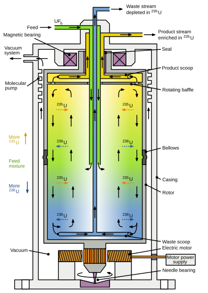
| 12:34, 12 January 2020 |  | 570 × 800 (130 KB) | Inductiveload | {{Information |description={{En|Simplified diagram of a gas centrifuge used for uranium isotope separation with a countercurrent circulation for increased separation. The current in this example is induced by the bottom (waste) scoop, and the product scoop is behind a baffle, which is attached to and rotates with the rotor, to prevent it setting up equal but opposite current. The uranium diffuses across the radius of the rotor, with <sup>238</sup>U migrating to the periphery and <sup>235</su... |
File usage
The following page uses this file:
Global file usage
The following other wikis use this file:
- Usage on ckb.wikipedia.org
- Usage on fa.wikipedia.org
- Usage on uk.wikipedia.org

